Safety note: This is high-energy electrical work. Follow local code, de-energize before handling conductors, use properly rated DC protection devices, and hire a qualified electrician/installer if you are not comfortable verifying polarity, torque, and fault protection.
Why split-phase matters off-grid
In the realm of off-grid living—whether you are outfitting an RV, a remote cabin, or a marine vessel—reliable power is not just a luxury. Split-phase systems (120V and 240V AC) deliver grid-like convenience for everything from household appliances to heavier 240V loads.
The Alchemy Industrial 120V/240V Split-Phase Power Kit is built around Victron components such as Quattro inverters and the Cerbo GX. Alchemy preconfigures the software side for split-phase operation, but the physical install still demands careful wiring, protection, and code compliance.
Split-phase from first principles
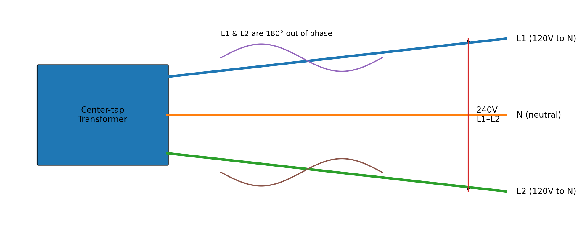
Figure: Split-phase concept (120V legs + 240V across L1–L2).
Split-phase power is a 240V system with a center-tapped neutral: you get two 120V legs that are 180 degrees out of phase. That arrangement supports 120V loads on either leg and 240V loads across both legs, while balancing current so one side is not overloaded.
From a first-principles view, current and heat follow resistance: imbalanced or undersized conductors increase losses and temperature. A well-built split-phase system is about predictable current paths, controlled fault energy, and stable monitoring—so you can run real loads confidently.
What is in the kit (high level)
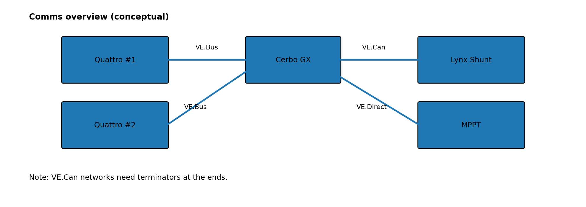
Figure: Communications overview (VE.Bus / VE.Can / VE.Direct, conceptual).
A typical Alchemy split-phase kit centers around:
Two Victron Quattro 48/10000/140 inverters configured for split-phase output
Cerbo GX for monitoring, control, and system coordination
Lynx DC bus components (Distributor + Shunt) for protected DC distribution and accurate current measurement
Victron SmartSolar MPPT controller(s) for solar charging
Pre-selected fusing and DC-rated disconnects/breakers appropriate to the kit design
Preconfigured does not mean prewired. The kit is designed to integrate cleanly, but your installation still determines safety and performance.
Safety: treat fault energy as the real hazard
A 48V battery bank can deliver thousands of amps into a short. PV strings are energized whenever there is light. AC outputs can be lethal. The practical rule is simple: de-energize and verify before you touch anything.

At minimum, before doing wiring work:
Open the battery disconnect and verify DC bus voltage with a meter
Turn PV isolators off and cover panels if needed
Trip or open all AC breakers feeding or supplied by the inverter system
Use insulated tools, correct torque, and strain relief; re-check polarity before landing conductors
If you are not comfortable using a multimeter to confirm polarity and voltage, hire a professional. This is not gatekeeping—DC arcs do not self-extinguish the way AC arcs often do.
DC architecture: the Lynx stack and why order matters
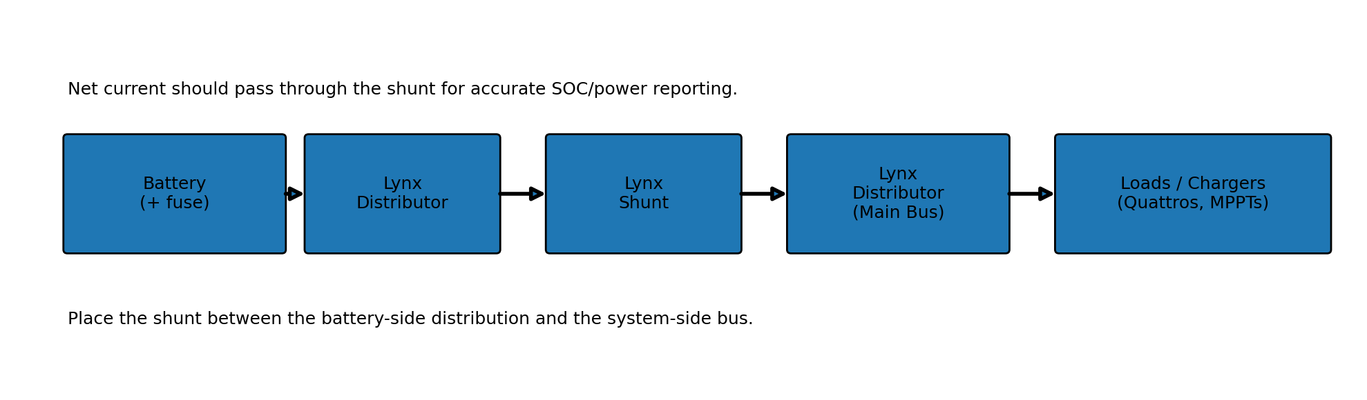
Figure: Example DC current flow through the Lynx stack (conceptual).
The Lynx stack functions as a modular DC bus. A common layout is: Battery-side Lynx Distributor -> Lynx Shunt -> Inverter-side Lynx Distributor (main bus).
That ordering is intentional. The shunt needs to see net current flow (charge in and discharge out) to report accurate measurements. A shunt works by measuring a small voltage drop across a known resistance (Ohm’s law: I = V/R), so placement matters.
Cabling and overcurrent protection
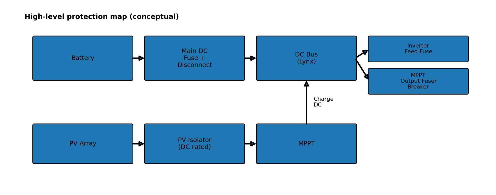
Figure: Protection map (conceptual placement of fuses, disconnects, and isolators).
Overcurrent protection exists to protect conductors and limit fault energy. DC ratings are critical—AC-only breakers may not interrupt DC fault current safely.
For Quattro inverter feeds, Victron commonly recommends high-current fusing and low-resistance cabling to reduce voltage drop. Using parallel conductors can reduce resistance and share current when done correctly (matched lengths, proper lugs, correct torque).
As a practical check, measure voltage drop under load (battery terminals vs inverter DC input). If drop is excessive, re-check cable size, crimp quality, and connection torque.
Install sequence that prevents mistakes
A reliable workflow is: DC bus first, comms next, PV and AC last. This isolates problems and keeps the system stable during commissioning.
A typical sequence looks like this:
Verify parts, fuse values, and that all disconnects/breakers are open/off
Mount the Lynx stack and land battery cables and main fuse per your battery spec
Land Quattro DC feeds through the intended fused positions; torque to Victron spec
Land MPPT outputs through DC breakers to fused positions on the bus
Wire communications: VE.Bus (Quattros), VE.Can (shunt), VE.Direct (MPPTs) to the Cerbo GX
Wire PV to isolator (off), then to the MPPT PV input
Wire AC input/output per local code: L1/L2/neutral/ground to the appropriate panels and breakers
Why this order? You establish a known-good DC backbone and monitoring first, then add energy sources and loads after you can see and verify system behavior.
Commissioning and first power-up
Commissioning is a checklist, not a vibe. Start with everything off/open, then energize one subsystem at a time while watching the Cerbo GX.
Typical flow: connect battery (Cerbo boots and shows DC voltage), enable the Quattros and confirm AC output (120V line-to-neutral and 240V line-to-line), then enable MPPT output breakers and PV isolator to confirm charging, then finally bring in AC input (shore/generator/grid) and connect loads.
Common issues and what they usually mean
Most early issues trace back to a short list: wiring order, polarity, missing terminators on comms networks, incorrect breaker/fuse placement, or voltage drop under load.
Examples: if the shunt is not visible, check VE.Can wiring and terminators; if the inverter trips on low voltage under load, quantify voltage drop and confirm the battery/BMS current limits; if PV charging is missing, verify PV voltage at the MPPT input with isolator on and confirm protection devices are closed and correctly rated.
Maintenance and support

After initial run time and thermal cycles, re-torque high-current connections to spec (thermal expansion can loosen lugs). Keep ventilation clear, inspect cabling for strain or abrasion, and periodically review logs in the Cerbo GX.
When asking for help, clear photos of the DC bus, protection devices, and Cerbo device list/screenshots speed up troubleshooting dramatically.
Closing thoughts
Installed correctly, this split-phase kit delivers scalable off-grid power with clean monitoring and predictable protection. The big idea is simple: match loads to energy storage, and design protection so faults are interrupted quickly and safely.
If you are adapting the kit for a specific battery, marine environment, or a particular load profile, the details matter—especially corrosion control, bonding, and conductor sizing.